Friday, November 7, 2014

Power comparison of ETSI channels in the 5GHz spectrum

If you are a WLAN engineer in the EU you probably need to know something about channels in the 5GHz band. Three main reasons come to mind. First is that being a WLAN engineer requires you knowing it, the second is that you probably get frequent "What is the max power your APs operate at?" and the follow up "How much do your APs cover compared to vendor X?" questions.

For the sake of pragmatism I'll be naming these two bands as 2,4G and 5G.


I've been asked this quite a bit in my time and I've found that the answer isn't as straight forward in the 5G as it's in the 2,4G band and for the WLAN designer adds a few variables to consider when planing a WLAN network.

I've come across a formal document specifying the use and operation of the UNII spectrum in the ETSI regulatory domain and what I found was intriguing. The FCC in the USA devides the 5GHz band into 4 subsets: UNII-1, UNII-2, UNII-2e and UNII-3 sub-bands. In the EU, to the best of my knowledge, we only use 1, 2 and 2e combined into 2 blocks. The UNII1 and 2 being in one block (A) and 2e in another (B). The two blocks have different usages, with block A permitted indoors only and block B permitted indoor or outdoor.


Each sub-band has a different number of channels available with 1 and 2 having 4 20MHz channels and 2e having 11 20MHz channels. The most intriguing thing I found were the EIRP allowances of those bands. As you can see from the below graph UNII-1 has a max EIRP of 23dBm (200mW), UNII-2 20dBm (100mW) and UNII-2e a whopping 27dBm (500mW). Below is the picture I painstakingly constructed with all the channels, EIRP, DFS and even boundaries - feel free to share.


The power difference among sub-bands means you can expect cell sizes to vary depending on the current channel used by a particular AP. 

But today's WLAN implementations aren't about how much you cover, but rather the capacity and rate-over-range (RoR) characteristics each cell has to be able satisfy different types of devices and services running on them. A sharp drop off at the edge is also very important to limit co-channel interference (CCI) as much as possible. So planing with this graph in mind wouldn't be too bad of an idea.

Another thing to consider here is the comparison with the EIRP in the 2,4G ISM band. Under ETSI max EIRP for 2,4G is 100mW (20dBm) (there might be exceptions) which is the same as the UNII-2 sub-band. The difference between 2,4G and 5G is roughly 6dB which means UNIIs 1 and 2 are somewhat handicapped. This lower EIRP means that the "coverage" of a particular AP working in those bands compared to 2,4G will be lower, maybe even to a point where you will need a second AP working just on 5G to produce the same coverage. Although that said, the noise floor will dictate that also and since 2,4G is getting more and more congested, the difference might not be that great these days.

But jumping on UNII2e wagon isn't as straight forward as well, since one has to consider other factors, like the fact it's under DFS rules and stations that don't support 11h can't probe which can make it a challenge for VoWiFi.

So I hope I've given you something to think about when designing your next WLAN and/or when troubleshooting an existing one. 

Comments and discussions are welcome as always.

Tuesday, September 30, 2014

Make a wall in Ekahau Site Survey

If you consider your self a WLAN designer, you're going to have to use a Site Survey tool and knowing how to construct walls in it will be the key to success. In this post I'll explain how to make a wall in Ekahau Site Survey software tool which as of this writing is on software version 7.6.2.

Ekahau Site Survey (ESS for short) comes predefined with a couple of walls but I'm yet to use any of them for a simple reason that no 2 walls are alike. This is due to the fact that walls in ESS are 3D modelled and any difference in thickens and/or attenuation value per meter will impact the result when modelling RF signal penetration through it.

To fully understand why this is important you can imagine an AP in front of a 10cm thick wall with some kind of attenuation level, for ex. 50dB/m. When a narrow beam of RF signal from the AP penetrates the wall perpendicularly i.e. hits the wall head on, it will loose a certain amount of energy while passing through those 10cm of wall material. But when another narrow beam of RF signal from the same AP hits the same wall at an angle, that distance traveled through the wall will be greater. If we take an example of 45° angle the distance traveled through the wall would be just over 14cm or 40% more than when the beam would hit it straight on.

So to compare the attenuation of the two beams:
- the head on beam would attenuate by 5dB
- the 45° beam would attenuate by 7dB.

Now if we were to use a predefined wall from ESS that would be for example 15cm instead of our 10cm with 50dB/m the following would be true:
- the head on beam would attenuate by 7,5dB (Δ of 2,5dB to the example above)
- the 45° beam would attenuate by 10,5dB (Δ of 3dB to the example above)

So it is important to get your measurements right in order to construct a proper wall in ESS and be able to make the right WLAN design for the building.


NOTE!
This post is only relevant if you are still using a version of ESS before v8. As of ESSv8 constructing a wall is made so much easier in the GUI. Ekahau indubitably made this change in response to this post. A fact which they will surely deny in public, but one that is true. OK, that last sentence is probably a fiction of my imagination, but that won't stop me from putting it in my CV.

Where to start?

To construct a wall you'll need to edit 2 files in your ESS installation directory. In the "/conf" directory you'll find various object types and properties files. That's where you'll also find the 2 files that you'll need to edit. These are "wallTypes.xml" that holds the actual data properties of a wall and the "wallTypes.properties" which is the key-to-name mapping file. The name in this file is the name that you'll see in ESS when selecting the wall button to draw the wall.


The "wallTypes.xml" file

The wallTypes.xml file consits of an xml schema. Each wall type is defined inside the <type> elements that house 4 other elements and a comment at the beginning. The comment here is especially useful in clearly explaining the properties of your wall and I suggest you use it too. The whole wall schema looks like the one below

<type id="wall_id">
        <!-- wall Xm YdB = Z dB/m -->
        <key>wall_key_mapping</key>
        <width>some width in meters</width>
        <absorption>attenuation per meter</absorption>
        <color>color HEX</color>
</type>

So you can just copy/paste one of the schemas and edit it. The elements inside the type element are pretty self explanatory but I'll go through them here:
  • key is the element used to map the wall property to the name of your property in the "wallTypes.properties" file
  • width is the actual width of the wall you are creating
  • absorption is the amount of attenuation the wall presents
  • color is the color you want it to appear in your ESS
I'm yet to understand what the id value in the type element is used for but you can make it the same as your key element just in case. 

The "wallTypes.properties" file

The key-to-name mappings file is pretty straight forward with lines of "key = name" mappings for each wall type that you make. Note here that ESS will add a dB attenuation value next to the name in brackets but not the width so I would suggest you name your wall with the width parameter, just so you'll know it. For example

my_key = My wall 10cm

and the wall will be visible like so


Don't forget to merge

There is one caveat of this feature. A new wall type will appear only for new projects you start after you have edited and saved both "wallTypes" files. For existing projects you have made before you edited those files you will need to use the File > Merge feature in order to be able to see the new wall in the drop down list of the wall. Then you can overwrite your previous project.

Final thoughts

Hopefully wall construction will become easier in the future as editing files is just not practical, plus there is a bug that appears whenever you make a change in an existing wall type ESS will show a duplicate of that wall in the GUI, but for now you know how to make a wall to fit the needs of the building you are planing the WLAN network for.

Sunday, August 17, 2014

802.11h in action

As you may or may not know, part of 802.11-2012 standard specifies the DFS or Dynamic Frequency Selection due to regulations that apply in most regulatory domains for RLANs in the 5GHz spectrum. DFS is there so that 802.11 radios don't interfere with other (more important) radar systems in the same radio vicinity. These are usually weather radars used by airplanes and having such a capability is a really good idea. DFS was originally part of 802.11h amendment which in turn is now part of the 802.11-2012 standard, but I'll refer to it as 11h.

In very short, the .11 radio in an AP wishing to operate on one of the UNII2e channels must continuously scan that channel for any presence of radar and must cease transmission on that channel if it detects a radar source. Some of the rules and procedures are written in this document from Cisco. 

The APs objective in changing channels is that disruption to the BSS is minimal and one of DFS procedures to help with this is the setting of the channel switch announcement element (CSA) in Beacon, Probe Response and/or Action management frames which tells it's associated STAs to which channel the AP is hopping and when. Below is an example of a beacon frame with a set CSA element. You can filter these frames out of a capture with "wlan_mgt.csa.channel_switch_mode" filter in wireshark.
The count value is the value of remaining beacons that will be broadcast on the current operating channel. The number here is 20 which indicates that 20 beacons (about 2 seconds) including this one are left before the channel change to channel 128 will be done. This number is decreasing with every sent beacon and when it reaches 1 you won't see another beacon or any other frame from the AP broadcasting BSS on the channel.

This assisting of changing channels isn't a guarantee that the STAs will actually accept the change and follow the AP to the new channel but most STAs will. STAs following the AP is only logical to do since the AP is handing the STA a new pipe to the net on a plate, but not all are made the same and some can switch to a new or even different BSS if they so choose.

If you've read this far first a thank you, and if you're asking your self why am I writing about this or who cares about channel changes I just wanted to  point out one vendors clever use of this function. Ruckus Wireless APs employ what their marketing calls ChannelFly. What their APs do is basically periodically hop through available channels in search of the one with best throughput characteristics. 'Everybody uses that. It's called background scanning' I hear you saying. Well CF differs from background scanning in that it doesn't go off channel to scan a different channel, but it just changes channels and operates on a new channel and takes measurements on that one and then hops again with the point of finding the one with the best characteristics of throughput and capacity. Each time it hops it uses the CSA element in it's beacons to hopefully take all it's associated STAs with it. 'Hopefully!?!', well for the most it does so without a problem. I've found many 5GHz STAs follow the AP without a problem, but some STAs might cause some problems. I have an HP laptop that operates in the 2,4GHz only and is supporting 11h, but upon a channel change it just gets lost and I have to disable/enable the NIC to get it running again.

My recommendation for CF would be to try it and see, but I consider it pretty safe when enabled on the 5GHz. For the 2,4GHz I suggest you try it and see if any STAs have problems when the AP is changing channels.

Monday, August 4, 2014

Fast & furious WLAN dB math

This post is a different look on Keith Parsons' "Easy dB Math in 5 minutes" but by no means a replacement. I've found that I learn thing faster if I see them from different perspectives and this is just that, a different perspective on the same subject.

There are only 2 things that you need to know really. The first is the linear to logarithmic conversion which Keith describes in Rule #2. This is what you need to remember.

+3dB = times 2 in linear form
-3dB = devide by 2 in linear form

And the other

10dB = 10 in linear form

The last one is important at the beginning when picking a reference point from which to start from. For about 99,9% of things in WLAN design the only 3 reference points will be 10dBm, 20dBm or 30dBm or 10mW, 100mW and 1000mW in linear terms. 

To convert it from one to the other just remember this: The number of zeroes in linear defines the first number of the dBm value and then you just ad a zero after that. For example

1000mW has 3 zeroes which you write as 30 and get the dBm value

And for the other way around the first number in dBm value (or dB or any other dBx value) defines the amount of zeros you add after number 1. For example

20dBm needs to have 2 zeroes after 1 or 100mW

Learn by doing

So to put this to practice, I've said that picking the right starting point is the key to fast conversion. For example, if we wanted to convert 27dBm to mW where would we start. The reference needs to be such that you can either add up to or down from it 3dB to the specified dBm value (27dBm) and then simply convert that to linear value. 

Let's first try to use 20dBm as reference. If we try to add up 3dB from that we couldn't get to 27dBm as 

20dBm +3dB + 3dB is 26dBm and
20dBm +3dB +3dB +3dB is 29dBm

So a better reference would be 30dBm since
30dBm -3dB = 27dBm

Since we know that 30dBm needs to have 3 zeroes after number 1 and -3dB means we need to divide that by 2 we can calculate that

1000mW divided by 2 is 500mW

We can make another example and convert 19dBm. In this example either 20dBm nor 30dBm would be the right starting points since we can't subtract 3dB from either of those to get to 19. But if we take the reference of 10dBm we can count up 3dB to it like so

10dBm +3dB +3dB +3dB = 19dBm

which translates to

10 x2 x2 x2 = 80mW

So as you can see it's pretty easy and hopefully you'll be translating linear to dB and vice versa easier now.

Tuesday, May 6, 2014

Give you WLAN NIC a monitor job

1. Use airmon-ng to put your WLAN NIC into monitor mode. With
$ airmon-ng start wlanX
you create a "monY" interface used for capturing frames. If this is the first monitor interface you'll make it will probably be named as "mon0"
2. Check if your interface is working with "airodump-ng". Sometimes it doesn't  which will require you to either re-plug your NIC or even reboot your Linux maschine.
$ airodump-ng monY
If you see networks and other info appear there on the screen it's working.

3. Now set your card to listen only on a specific channel. Some prefere to use "airodump-ng" for that but I prefer "iw" since I can set regulatory domain and channel width with it. First thing is to set the regulatory domain of your NIC which will enable you to use channels of interest. You set the regulatory with
$ iw reg set XX
where XX is one of the countries from this list http://en.wikipedia.org/wiki/ISO_3166-1_alpha-2. 
After that check to see if the setting of regulatory domain took hold with
$ iw reg get

4. For the last part you can set a specific channel to listen on and the channel width if you are using channel bonding. The syntax is
iw phy <phyname> set channel <channel> [HT20|HT40+|HT40-]
which means that we first need a "phyname". If you didn't remember WLAN NICs phy name in step one you can get it with the "iw list" command. It will list all of your NICs information which there's a lot of, so I suggest you grep what you need with something like
$ iw list | grep phy
If you've got only one phy you'll know which name to use. If you've got more than one then you'll need to know on which one you have enabled monitoring. You can do this by setting a channel on one phy and check if the channel is fixed by either using wireshark or better tshark which dumps captured data directly in the terminal. With
$ iw phy phy2 set channel 132 HT40+
you set your NIC to listen on bonded channel 132. You could use a frequency (5660) instead of channel number if you prefer which might be a good idea for later when we will check our settings.
For listening on bonded channels use either HT40+ or HT40- option. In the above option I used the HT40+ option. Be careful here as you can't just use any option with a selected channel. Below is a list of Supported 40MHz combinations of 802.11n channels in the 5GHz spectrum.
(36,1) (40,-1); (44,1) (48,-1); (52,1) (56,-1); (60,1) (64,-1); (100,1) (104,-1); (108,1) (112,-1); (116,1) (120,-1); (124,1) (128,-1); (132,1) (136,-1); (149,1) (153,-1); (157,1) (161,-1)

5. To check if everything is owrking now tshark or wireshark, whichever you prefer. For tshark use the following

$ tshark -i monX -T fields -e radiotap.channel.freq

Here I say to tshark to use my monitor interface (-i) monX (X is whichever was created) and to display only specific fields with the "-T fileds  -e radiotap.channel.freq". In this case I'm interested only in frequency to see if my card is working properly.
You should see numbers that correspond to the frequency you have set on your adapter and they should all be the same all the time. It will require you to use an adapter that can produce "radiotap" headers. For more on those I suggest you read Nigel Bowden's blog here http://wifinigel.blogspot.com/2013/11/what-are-radiotap-headers.html

Wednesday, April 16, 2014

Capturing 802.11 frames with Ruckus Wireless access points and Wireshark

Since many problems can be resolved only by closely inspecting packets traversing the air the essential daily requirement for any WLAN engineer is capturing and then analyzing them.

These days vendors are increasingly integrating packet sniffing tools into their products. Since there are many APs out there with a higher count of internal radios than their USB dongle counterparts it actually makes allot (if not the only) sense to use an AP for the sniffing job. The previous statement is true only if you're capturing frames from a 3x3 or higher AP otherwise a proper USB dongle could be used.

This post (more of a how-to than a post) will show you how to capture packets from a Ruckus Wireless (RW) AP either in stand-alone or a ZD controlled mode. For this you will require:
  1. An RW AP - any recent will do
  2. A ZD, but it works without it also
  3. Wireshark
The first thing to do is to put your APs radio into monitor mode or as RW calls it "capture" mode. You can do that in 2 ways. You either SSH to an AP and enable it there, or if the AP is ZD controlled you can enable it via the ZD web GUI. Doing it via ZD you can probably do it faster, but you can't set all of the available options that way.
The other thing is to setup you Wireshark to capture frames from the network connected AP.


SSH to the AP and enable capture mode

Logging in is easy. You need to know the APs IP address and login credentials. Once in the CLI enable the capture mode for which you have 2 options.
  • stream mode where you stream the frames directly to Wireshark
  • save mode whit which you save a finite amount of frames and send them via TFTP
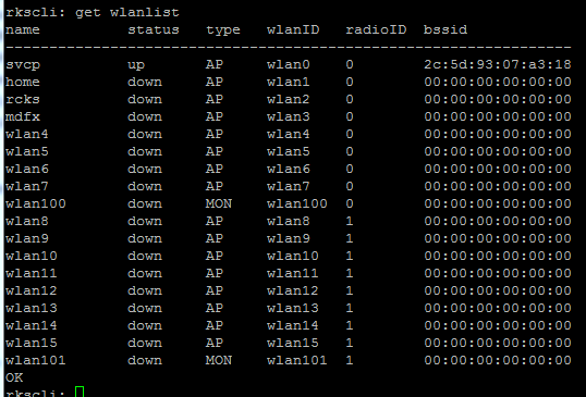
Since APs can have 2 radios you need to specify which radio should be configured for capture. Each radio has one monitor (MON) interface. You can get a list of interfaces that an AP supports with the command

# get wlanlist 

which in the case of a dual-band AP produces something like this

Here you can see the AP has 2 monitor interfaces (MON) you can use to capture on:
  • wlan100 is on the 2,4GHz and
  • wlan101 is on the 5GHz radio
Here's the capture command in full

set capture <wlan name> {idle|[stream|local][-no[b][c][d][p]] [showLDPC]}
     -> -nob: nobeacon
     -> -noc: nocontrol
     -> -nod: nodata (not implemented yet)
     -> -nop: nopromiscuous
     -> -no[b][c][d][p]: any combination
     example: set capture wlan100 stream-nobcp
     -- Set Packet Capture state/filter

So you have various options you can enable. Mostly you can disable some types of frames to be sent over the wire if you wish, but you can filter those out even later via Wireshark filters. So to get started quickly just input the following

# set capture wlan10x stream

where x is either 0 or 1, depending on the band you wish to capture on.


Setting the channel on stand-alone APs

When capturing on stand-alone APs the channel will change periodically so you will probably want to lock the AP on a particular channel while capturing.

The CLI command for this is the following

set channel <wifi name> {<channel>|auto}
       -- Set the radio channel

Again on a dual-band AP you set the channel for each radio separately. For example if you would like to set the 2,4GHz radio to channel 3 (2422MHz) you would do the following

set channel wlan100 3
OK

Then check with the following

get channel wlan100
wlan100 Channel: 3 (2422 Mhz) (Manual Channel Select)
OK

Setting capture mode of a ZD controlled AP

The other way to setup capture on an AP or a group of APs is to do it over the ZD interface. For this you do the following

1. Go to Administer :: Diagnostics and enable capture on selected band and APs and Add to capture APs list


2.Once APs are in capture list choose either "Streaming" or "Local" mode and click "Start"


Next comes the Wireshark part.


Setting up Wireshark

Now that you've got your AP setup you need to get your Wireshark up and running which involves quite a few steps.
1. Configure capture options by clicking on the icon or hitting CRTL+K
2. Click on the Manage interfaces button to configure the Remote interfaces.
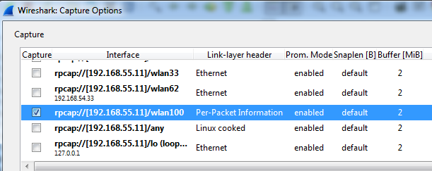
3. Click Add and input the APs IP address and OK it. You will see a list similar to the one below
Now select all the check boxes on the right except the wlan100/wlan101. This will hide all the interfaces except that one. Since it's the only one to capture on it makes sense to do it, however it's optional and you can leave everything visible.
4. Now click Apply and then Close
5. Now select wlan100/wlan101 and click either Start or Close. If you close at this point you will start a capture with CTRL+I and select the interface to start the capture on.

Hooray packets


NOTES
1. Only one of the two available monitor interfaces can be active at one time.
2. An SSID must be configured for operation, although broadcasting of the SSID can be suppressed.
3. You can stream packets only to a Windows machine since it uses winpcap that allows for this.